
The Backbone of Modern Vehicle Communication
Whether you're a student stepping into automotive systems, an engineer working on embedded projects, or just curious about how cars talk, understanding the Controller Area Network (CAN) is essential. It’s the invisible electronic nervous system inside modern vehicles, enabling everything from engine control to your car’s entertainment system to communicate efficiently.
In this article, we’ll cover what CAN is, why it matters—and how you can start exploring it with tools like ATI’s CANary interface and CANLab software.
What is CAN Bus?
The Controller Area Network (CAN) is a robust communication protocol designed to let microcontrollers and devices communicate with each other without a central host computer. Developed by Bosch in the 1980s, it was originally created for automotive systems but is now used in various industrial and embedded applications.
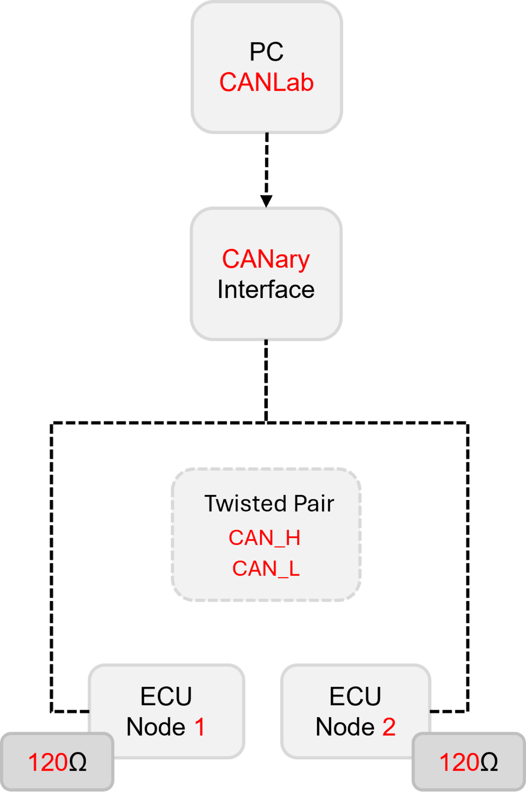
Imagine dozens of Electronic Control Units (ECUs) inside a car—engine, ABS, airbags, windows—all needing to share data. Rather than wiring each component individually (a wiring nightmare), CAN allows all of them to connect to the same two-wire bus, sending and receiving standardized messages.
Key Features of CAN
- Single wire CAN – primarily found in specialty automotive applications and emphasizes low cost. Defined in the SAE 2411 specification, single wire CAN uses only one single-ended CAN data wire, as opposed to the differential CAN wires found in most applications.
- Two-wire system (CAN_H and CAN_L) – uses differential signaling for noise immunity
- Broadcast communication – one node sends, many can listen
- Prioritized messaging – ID-based arbitration ensures important messages get through
- Error detection & handling – CRCs, ACKs, and fail-safe features
- Speed – typically up to 1 Mbps (or 8 Mbps with CAN FD)
How CAN Messages Work
A CAN message isn’t like an email with a “to” and “from”—instead, every message has an identifier (ID) that signifies what kind of data it contains (e.g., “engine RPM” or “brake status”). Any ECU that’s interested in that kind of message simply listens for it.
Each message contains:
- ID (11 or 29 bits)
- Data Length (0–8 bytes for CAN 2.0, up to 64 for CAN FD)
- Data Payload
- CRC & error bits
What You Need to Get Started
To work with a CAN network, you’ll need:
- A CAN interface – to connect your PC to a CAN network
- Software – to monitor, log, and send messages
- A target network – either a simulator, bench ECU, or development board
ATI's CANary and CANLab: The Ideal Starter Kit
CANary is ATI’s compact, USB-powered CAN interface that makes it easy to start capturing and analyzing CAN traffic. It’s:
- Plug-and-play
- Supports standard CAN and CAN FD (with CANary FD)
- Lightweight and portable
Pair it with CANLab, ATI’s CAN message viewer, logger, and analyzer. It’s ideal for:
- Live message monitoring
- Custom message filtering
- Logging and replaying real-world CAN data
- Learning through scripting and automation (more on that in future blogs!)
Then you need your DBC file. What’s that?
A DBC (Database CAN) file is a plain-text specification that describes how raw CAN frames on a bus map to meaningful, human-readable signals.
| Element | What it defines |
| Messages | Each CAN ID (identifier) that appears on the bus—along with its payload length (0-8 bytes for Classic CAN). |
| Signals | Bit-level slices within the message payload that represent individual data items (e.g., engine RPM, steering-angle). A signal entry specifies: start bit, length, byte order, signed/unsigned, scaling factor, offset, physical units, and value ranges. |
| Nodes | Which electronic control unit (ECU) transmits or receives each message. |
| Additional metadata | Comments, value tables (enumerations), multiplexing rules, diagnostic info, etc. |
How it is used when you “connect” to a vehicle CAN network
- Physical interface & bus parameters
You plug a CAN interface (EG CANary) into the vehicle’s diagnostic connector (OBD-II, J1962) or directly onto a harness breakout. Set the bus speed (e.g., 500 kbit/s) and, if applicable, CAN FD data-rate. - Load the DBC into your tool or code
• CAN analyzers EG ATI’s CANlab parse the DBC.
• The tool now “knows” how to decode each CAN ID. - Live decoding / logging
As frames stream in, the software matches the ID to a message definition in the DBC, extracts signal bits, applies scaling × factor + offset, and presents real-world values (e.g., RPM = 2560 rev/min instead of “0x0A00”). - Transmission / simulation
Conversely, you can compose frames by assigning signal values (e.g., set “CruiseControlSwitch = ON”); the tool packs the bits per the DBC and sends the correctly formatted frame onto the bus. This is essential for HIL/ECU simulation, test benches, or reverse-engineering. - Maintainability & collaboration
Because the mapping is externalized in the DBC, engineers can share, version-control, and update signal definitions without changing the decoding code itself.
In short: A DBC file is your translation dictionary between raw CAN frames and meaningful engineering signals, enabling any compliant software or script to monitor, log, analyze, or inject data on a vehicle CAN network with minimal manual bit-twiddling.
What’s Next?
Now that you know the basics of what CAN is, how it’s decoded with a DBC file and what tools you need to get started, the next blog will walk you through setting up your first CAN network with real tools, proper termination, and message tracing.