
After setting up your first CAN network, the next step is understanding what the messages on the bus actually contain. Every communication on the Controller Area Network (CAN) takes place in the form of a structured message called a frame. In this blog, we will examine the structure of CAN frames, the differences between frame types, and how tools like Accurate Technologies' CANLab software can be used to decode, visualize, and analyze CAN traffic effectively.
The Anatomy of a CAN Data Frame
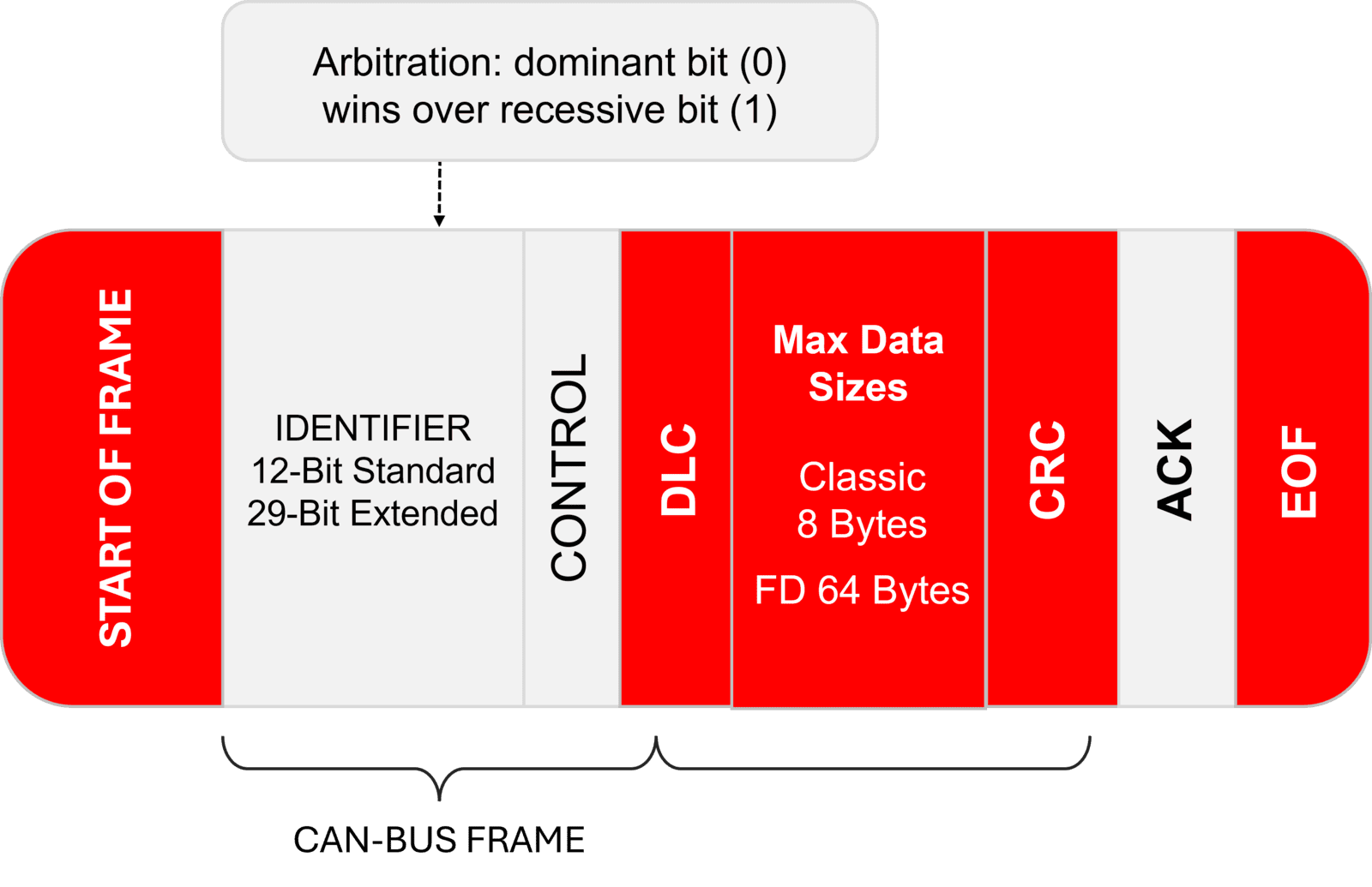
The data frame is the most common frame type and is used to transmit actual payload data between electronic control units (ECUs). Each data frame follows a standardized layout as defined by the CAN protocol specification.
Typical fields in a CAN data frame:
| Field | Description |
|---|---|
| Identifier (ID) | Specifies the message's priority and meaning. Lower ID values have higher priority on the bus. |
| Remote Transmission Request (RTR) | Indicates whether the frame is a data frame (RTR = 0) or a remote frame (RTR = 1). |
| Identifier Extension (IDE) | Distinguishes between a standard (11-bit) and extended (29-bit) identifier. |
| Data Length Code (DLC) | Indicates the number of data bytes (0 to 8 for Classical CAN, up to 64 for CAN FD). |
| Data Field | Contains the actual message payload. |
| CRC | A cyclic redundancy check for detecting transmission errors. |
| ACK | An acknowledgment bit to confirm successful receipt. |
| End of Frame | Marks the conclusion of the transmission. |
Interpreting what these bytes represent depends on the system configuration and a DBC database that maps data to meaningful signals.
Standard vs Extended Identifiers
CAN frames use either standard (11-bit) or extended (29-bit) identifiers. The choice depends on the protocol and the application domain.
| Identifier Type | Bit Length | Typical Use Cases |
|---|---|---|
| Standard ID | 11 bits | Used in most automotive and industrial applications. |
| Extended ID | 29 bits | Required in protocols like J1939 and used when a larger message set is needed. |
Lower ID values have higher arbitration priority, which allows more critical messages to take precedence on the network.
Remote and Error Frames
In addition to data frames, the CAN protocol defines two other important frame types:
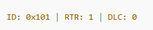
Remote Frame
A remote frame is used to request data from another node on the network. It contains the same identifier as the expected response but does not carry any data payload. When a node receives a remote frame, it responds with a data frame containing the requested information.
Example:
Error Frame
An error frame is automatically generated by nodes that detect a transmission error, such as a CRC mismatch or bit stuffing violation. Error frames are essential for fault-tolerant communication, although they are not typically visible in high-level monitoring unless explicitly enabled.
Byte Layout and Signal Decoding
While the data field of a CAN frame is limited to eight bytes in Classical CAN, each byte or bit can carry specific meaning based on how the system is designed. A single frame might include multiple signals with their own scaling, units, and positions.
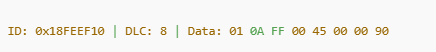
For example, a byte pair might represent a temperature signal using a scale factor and offset:
Raw value:
0x01 0A(decimal 266)Scale: 0.1
Offset: -40
Interpreted: (266 × 0.1) - 40 = -13.4 °C
To decode such values efficiently, engineers use DBC files, which describe the layout of data inside each frame. These files are critical for converting raw CAN data into human-readable signals.
Visualizing and Decoding Frames with CANLab
Accurate Technologies' CANLab software simplifies the process of interpreting and analyzing CAN messages by allowing users to apply DBC (Database CAN) files and view decoded signal data in real time.
Key features of CANLab include:
Raw Trace View: Shows message ID, timestamp, DLC, and data bytes in a time-ordered list.
Signal View: Uses DBC definitions to decode signal values, display physical units, and apply scale factors automatically.
Custom Filtering: Allows users to isolate messages or signals of interest.
Scripting Support: Enables custom test automation or post-processing using embedded scripting.
Graphing Tools: Displays signal trends over time for analysis or debugging.
Using CANLab, a raw message such as:
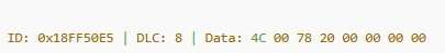
the above ID might be decoded to reveal:
Vehicle Speed = 100.0 km/h
Brake Status = Active
Steering Angle = -15.0 degrees
This decoding transforms binary traffic into usable engineering data for testing, diagnostics, and validation workflows.
Summary
| Concept | Description |
|---|---|
| Data Frame | Carries actual payload data across the CAN network. |
| Remote Frame | Requests a data frame from another node using the same identifier. |
| Error Frame | Signals transmission errors and helps maintain network reliability. |
| Standard and Extended IDs | Allow flexibility in network design and message prioritization. |
| DBC Files | Act as dictionaries, which can be used by development tools, to translate raw CAN HEX data into meaningful signal Names and physical Values. |
| CANLab | Enables real-time visualization, filtering, and decoding of CAN traffic. |
Wrapping Up
In Part 4, we will shift focus to the hardware side of CAN: wiring, termination, and electrical reliability. You will learn how twisted-pair cables, 120-ohm termination, and proper shielding practices help maintain signal integrity. We will also discuss how the presence of error frames in CANLab can serve as an early indicator of physical layer issues, such as noise, improper termination, or faulty wiring, and how these symptoms can guide further troubleshooting.