
In Part 1 of this series, we introduced the Controller Area Network (CAN Bus) and its role as the central nervous system in modern vehicles. Now, we’ll guide you through creating your first CAN network — from hardware setup to sending and receiving messages — using both entry-level components and professional-grade tools.
Getting Started: What You'll Need
Setting up a CAN network requires a few essential components:
- CAN-enabled devices or microcontrollers
- CAN transceivers to convert logic-level signals to CAN voltages
- Termination resistors to maintain signal integrity
- Wiring and power
- Tools for monitoring and diagnostics
Depending on your goals, the approach you take — and the tools you use — can vary significantly.
Option 1: Entry-Level Setup for Learning & Prototyping
If you're just starting out, an inexpensive, accessible setup might look like this:
- Two low-cost microcontroller boards (such as Arduino-compatible boards)
- CAN controller + transceiver modules (often based on MCP2515 and TJA1050)
- Jumper wires, breadboards, and power supply
- 120Ω resistors for bus termination
This DIY configuration is ideal for educational projects or proof-of-concept work. It allows you to observe CAN traffic and experiment with message transmission in a controlled environment.
Keep in mind: While affordable and easy to assemble, these systems lack the reliability, accuracy, and advanced functionality needed for real-world deployment or in-vehicle testing.
Option 2: Professional Tools for Development & Validation
For more complex applications — such as ECU calibration, diagnostics, or sensor data acquisition — engineering-grade tools are preferred. These solutions are purpose-built for the demands of vehicle and industrial development and often include:
- High-speed network interfaces (supporting CAN, CAN FD, LIN, and Ethernet)
- Robust data acquisition systems capable of integrating multi-sourced signals, such as analog, digital, and CAN
- Time-synchronized logging across multiple channels and sources
- Decoding and visualization support using DBC, A2L, and other standard file formats
- Software environments for real-time analysis, scripting, or calibration workflows
These systems are widely used by OEMs and Tier 1 suppliers for in-vehicle development, system validation, and production diagnostics.
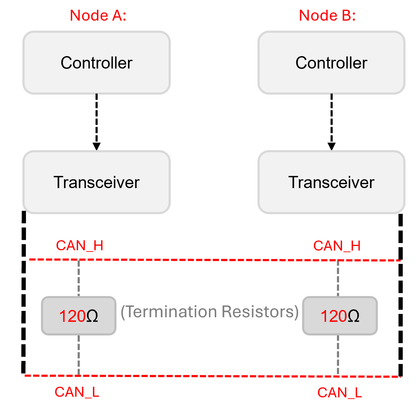
Wiring the CAN Network
A minimal CAN network includes two nodes connected in parallel over a twisted pair of wires:
- Connect CAN_H to CAN_H, and CAN_L to CAN_L
- Add 120Ω termination resistors at each end of the bus
- Ensure a common ground between nodes to avoid voltage differences
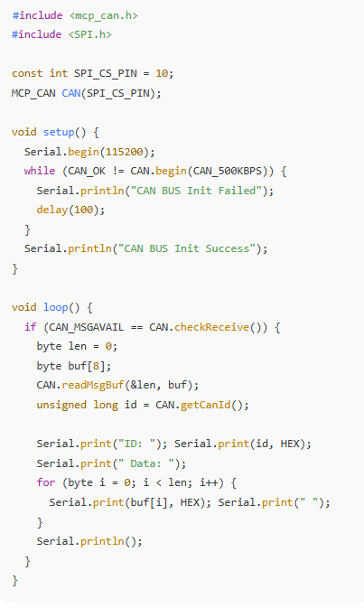
Sending and Receiving CAN Messages (Sample Code, C++)
Here’s a basic example using a microcontroller and CAN module (e.g., MCP2515) in the Arduino environment.
Transmitting Messages
Receiving Messages
Monitoring the Bus
With entry-level setups, monitoring usually involves sending and receiving raw or slightly decoded data over USB or other basic serial communication tools. For deeper insight and professional workflows, engineering-grade tools provide:
- Graphical trace views with timestamped CAN messages
- Real-time decoding using signal and message databases (DBC files)
- Data logging, filtering, and message injection for debugging
- Synchronization of CAN data with other data sources like analog, digital, or vehicle sensor inputs
These capabilities are critical for debugging complex systems, testing fault responses, or validating ECU behavior under real-world conditions.
Choosing the Right Setup
| Feature | Entry-Level Tools | Engineering-Grade Tools |
| Intended Use | Learning, Prototyping | Development, Calibration |
| Message Decoding (DBC Support | ❌ No | ✅ Yes |
| Time-Synchronized Logging | ❌ No | ✅ Yes |
| Reliability in Harsh Environments | ❌ No | ✅ High |
| Software Integration | ❌ Minimal | ✅ Advanced |
| Cost | 💲 Low | 💲💲💲 Medium to High |
Wrapping Up
At this stage, you’ve learned how to build a basic CAN network, wire the physical layer correctly, and send or receive raw messages using both entry-level and professional-grade tools. Whether you're experimenting with microcontrollers or deploying high-performance tools for validation and calibration, a solid foundation in CAN network setup is critical.
But setting up the hardware is just the beginning.
In Part 3, we’ll dive into what really travels across the CAN bus — the messages themselves. You’ll learn how to interpret standard and extended message identifiers, understand the role of data, remote, and error frames, and break down the byte layout used in actual message payloads. This knowledge is key to making sense of CAN traffic, decoding signals, and building reliable communication systems.