Inside an MDF4 File: Understanding the MDF4 Data Structure

September 18, 2026 09:34 AM - By Rachael

Part 2 - ASAM MDF4 Explained

In the first part of our ASAM MDF4 Explained series, we looked at what MDF4 is, why the format exists, and how it helps engineers manage increasingly large and complex measurement datasets.

Now it’s time to look inside the file.

An MDF4 file may appear to be a single .mf4 file on your computer, but internally, the information is organized into a network of interconnected blocks. These blocks separate different types of information, such as file metadata, measurement channels, timing, conversions, and the recorded data itself.

Understanding this structure helps explain how MDF4 can efficiently organize everything from a handful of measurements to extremely large vehicle test recordings containing thousands of channels.

MDF4 Uses a Block-Based Structure

Unlike a simple format such as CSV, MDF4 does not organize an entire recording as one large table of rows and columns.

Instead, MDF4 uses specialized blocks. Each block has a particular purpose, and links between the blocks describe how the different pieces of the measurement relate to one another.

At a simplified level, an MDF4 file can be thought of as:

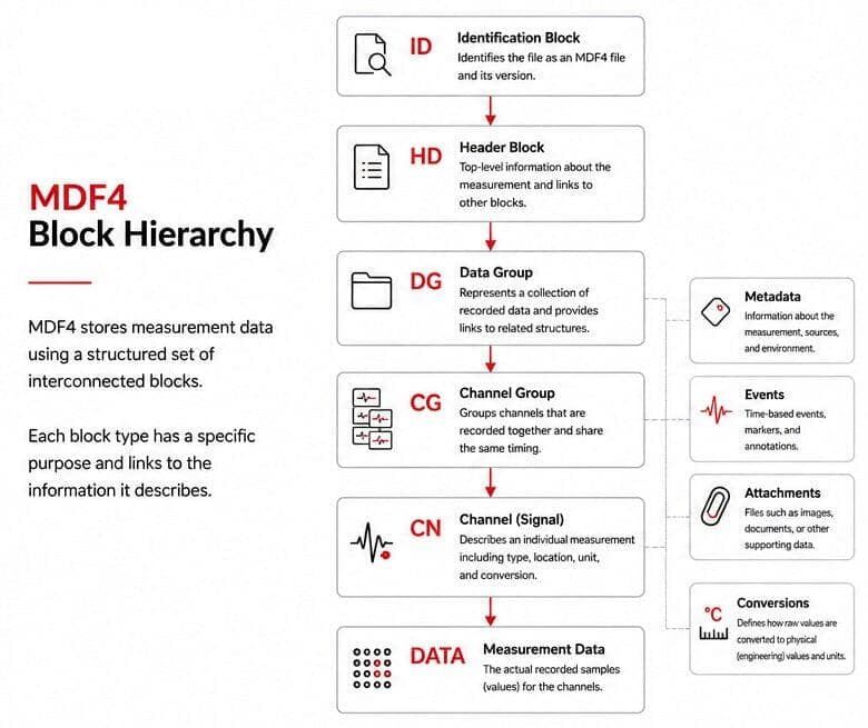
File → Data Groups → Channel Groups → Channels → Measurement Data

Additional blocks provide information such as conversions, units, source information, events, attachments, and metadata.

This structure is one of the reasons MDF4 can accommodate complex measurements with different sampling rates and data sources without forcing everything into a single uniform dataset.
The Identification and Header Blocks

Every MDF4 file needs a starting point.

The Identification Block (ID) identifies the file as an MDF file and provides basic information about the MDF version.[JK1.1]

From there, the Header Block (HD) acts as the primary entry point into the MDF4 structure.

The header can provide general information about the measurement and links to other important structures within the file. Think of it as the top level of the recording rather than the place where the measurement samples themselves are stored.

From the header, software reading the file can begin navigating through the blocks that describe the measurement.

Data Groups: Organizing Recorded Data

Below the header are Data Groups (DG).

A data group represents a collection of recorded data and provides links between the description of that data and the blocks containing the actual records.

An MDF4 file can contain multiple data groups.

This is important because a measurement session may contain information originating from different sources or organized in different ways. MDF4 does not require every piece of recorded information to fit into one universal structure.

Within each data group, the information is organized further using channel groups.

Channel Groups: Measurements That Belong Together

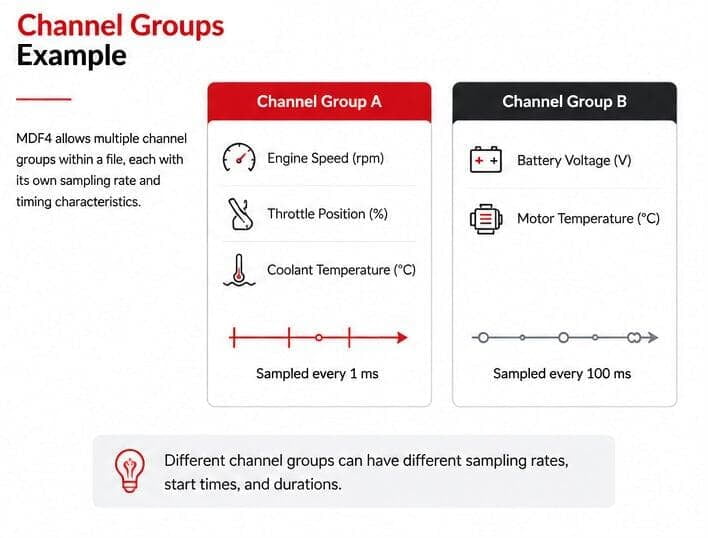
A Channel Group (CG) describes a group of channels whose values are stored together in records.

For example, imagine a test recording containing:

•  Engine speed
•  Throttle position
•  Coolant temperature

If these signals are acquired together, they may belong to the same channel group.

Another set of measurements recorded differently could belong to another channel group.

This organization becomes particularly useful when measurements have different timing or acquisition characteristics.

Rather than forcing every signal in the file into the same sampling structure, MDF4 can preserve how the data was actually recorded.

Channels: Describing Individual Measurements

Within a channel group are Channel Blocks (CN).

Channels represent the individual pieces of information engineers ultimately want to work with.

Depending on the measurement, a channel might represent something such as:

EngineSpeed
CoolantTemperature
BatteryVoltage
VehicleSpeed

The channel definition provides the information necessary to locate and interpret that measurement within the recorded data.

However, a channel name alone is not enough.

To turn recorded bits and bytes into useful engineering information, MDF4 may need to describe the channel's data type, location within a record, timing relationship, conversion, unit, and other characteristics.

That information is connected through the MDF4 block structure.

Master Channels and Time

Measurement data becomes much more useful when you know when each value occurred.

MDF4 uses the concept of master channels to establish the relationship between recorded samples and an independent variable, most commonly time.

Consider two groups of measurements:
Group A: sampled every 1 ms
Group B: sampled every 100 ms

The two groups do not need identical timestamps or the same number of samples.

Each can maintain its appropriate relationship to time.

This is an important distinction from a simple spreadsheet-style representation, where it can be tempting to place every signal against one universal time column.

MDF4 can preserve the original timing characteristics of different measurements.

Channel Conversions: From Raw Values to Engineering Values

The number stored by a measurement system is not always the number an engineer wants to see.

Suppose a channel contains a raw value of:
2150

That value might need a conversion before it represents a meaningful engineering quantity.

After applying the appropriate conversion, the result could become:
21.5 °C

MDF4 can describe this relationship using Channel Conversion Blocks (CC).

Conversions can range from relatively simple mathematical relationships to more complex conversion methods.

Separating the recorded value from its physical interpretation allows MDF4 to preserve both the original measurement and the information required to understand it.

Where Is the Actual Measurement Data?

So far, most of the blocks we've discussed describe the measurement.

Eventually, we need the actual samples.

MDF4 uses data-related blocks to store the measurement records themselves. Depending on how the file was created, these records may be stored directly or through additional structures designed to organize or compress the data.

This separation is important.

A channel block might tell an application:

This channel represents engine speed, uses this conversion, and occupies this location in each record.

The associated data blocks contain the actual recorded values.

Software reading an MDF4 file uses the information from these interconnected blocks to locate the appropriate samples and interpret them correctly.

More Than Channels and Samples

MDF4's block architecture also allows a file to contain much more than conventional signal data.

Depending on the recording, an MDF4 file can include information associated with:
•   Events
•   Attachments
•   Source information
•   Comments and descriptions
•   Conversion information
•   Bus and network data
•   File and measurement metadata

This allows an MDF4 recording to preserve context that might otherwise need to be stored separately.

For example, an engineer reviewing a measurement weeks or months later may need more than a graph of values. Information about the measurement source, events during the test, units, or channel definitions can be essential to understanding what happened.

How the Pieces Fit Together

A simplified MDF4 structure might look like this:
Identification Block (ID)
Header Block (HD)
Data Group (DG)
Channel Group (CG)
Channel (CN)
Measurement Data

Other blocks branch from this basic structure to provide conversions, metadata, source information, events, attachments, and other details.

The real structure can be considerably more complex, particularly in large measurement files, but this simplified hierarchy provides a useful mental model.

Instead of thinking of an MDF4 file as a giant table, think of it as a structured map of the measurement.

Some blocks tell you what was measured. Others tell you how it was measured, how to interpret it, and where to find the recorded values.

Why Does This Structure Matter to Engineers?

Most engineers will never need to manually navigate from one MDF4 block to another. MDF4-compatible software handles that work behind the scenes.

Understanding the basic structure is still useful.

It explains why MDF4 can handle signals with different sampling rates, why measurement values can have conversions associated with them, why a single file can contain multiple types of measurement information, and why MDF4 files can preserve significantly more context than a simple exported table.

When an MDF4 analysis tool opens a recording, it is effectively following this map, identifying the available measurements and turning the underlying data structures into signals, timestamps, units, events, and other information that engineers can work with.

Tools such as ATI VISION Data Analyzer (VDA) handle this interpretation automatically, allowing engineers to open and analyze MDF4 data without needing to work directly with the underlying block structure.

The structure may be largely invisible to the end user, but it is what makes that workflow possible.

What's Next: From Raw Measurement to Engineering Signal

We've now looked at the major building blocks that give an MDF4 file its structure.

But how does a value actually travel from the measurement system to the signal an engineer sees on screen?

In the next article in our ASAM MDF4 Explained series, we'll follow that process more closely, exploring raw measurement values, physical values, conversions, timestamps, master channels, and different sampling rates.

Understanding that journey helps connect MDF4's underlying file structure to the measurement data engineers use every day.

Rachael

Rachael